Hello everyone!
This is one small project which I had done with Abhinav Gupta some months back. In this experiment, I graduate from using simple RF communication to Xbee! 😀 Whoa! 🙂
Ok, so here is the basic problem statement. I need to develop a temperature sensing system such that the temperature from the sensor node is relayed to a co-ordinator sensor and then the co-ordinator node shows the user in a simple graphical form.
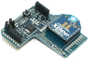
For the wireless communication, I used Xbee Series 2 modules with Arduino Board Shields. The shield looks like this :
The lower pins can be easily slided into an Arduino Duemilanove or even an Arduino UNO board. The shield is readily available on different portals selling electronics hardware related to Arduino boards. There are some XBee radios in the market which are almost the exact copy of the Xbee based radio modules (Open Source! ). Personally I wouldn’t recommend them for learning or experimental purposes because majority of the times, they are highly customised and they don’t give you freedom to work with the ones which are discussed in the community. This is a major backdrop of highly custom Zigbee protocol based shields. Buying the custom ones is always beneficial when they are going to be used for a specific operation. One more awesome thing about this shield is that you never lose out on the analog and digital pins of your micro-controller. There are female headers attached on the shield which basically allow you to easily connect the required circuitry to the arduino board. This shield doesn’t interfere with the working of the arduino board! Sweet! 😀
Ok, now coming to the Xbee radio. The radio is available in three types, namely Xbee Series Pro, Series 1 and Series 2. For all experimental purposes, using Series 1 and Series 2 should be enough. Xbee Series Pro is basically used when you need to have a better range and your application is specific. I have worked with only Series 1 and Series 2 modules. Ok, once the radios are bought, we need to code them. We should understand that the radios usually don’t have memory to store “codes” as such. There is enough memory to store the values of many parameters but not specifically a “code”. How do we set those parameters to get the Xbee working? Well, windows users may use a free software named X-CTU , specifically developed to store the values of different parameters of your Xbee. For Linux users, they can use any terminal softwares like HyperTerminal. But some of the custom radios are such that we always need to use their prescribed software only! A standalone Xbee Radio Module looks like this:
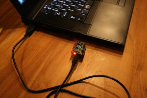
You may use it with a shield or you have another alternative. If your application isn’t micro-controller based, then you can surely go buy a Break Out board for Xbee and then power it separately or probably even have something like this made :
Such a Xbee can be powered using a laptop or that could be replaced by a single 9 v battery source too to make it portable! ( There are other issues which we come across if we want the sensor node to be completely independent! Those issues will be discussed in the upcoming posts! )
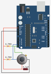
Ok, coming back to the problem statement, we used a temperature sensor namely Infrared Thermometer – MLX90614 which was bought from RhydoLabz. The reason to choose this particular sensor was that it had a wide ambient temperature range with enough resolution. The sensor has an inbuilt 17 bit ADC! That is one awesome feature of this sensor. Now we need to interface this particular sensor with our micro-controller board, ie the Arduino Board. On googling up for some time, we realised that a new library should be written for the sensor to be interfaced with an arduino board. The new library was written and the circuit diagram which we used was as follows:
(source – bildr blog)
Due to mismanagement from my side, my code has been lost somewhere! Someday I will surely work on it and push it on git. But for those who want a source code, they could probably include this in their libraries folder of the arduino software.
So now, this is how the system looks like. MLX90614 temperature sensor is interfaced with a micro-controller and a sensor node Xbee. There is another Xbee in the system which acts as a co-ordinator and receives the data packets from sensor nodes. Now if the co-ordinator sensor node is connected to a laptop or a server, on simple use of python’s “pyplot” library , we could generate different types of graphs. Using PHP, all of it can be hosted on a local host machine! This allows you to have the temperature of an area on your fingertips! We used python’s pyplot library to plot the graphs because it was damn easy! Python for sure is the best choice if you want less of code and more work to be done!
To set up a localhost on a Linux machine LAMP can be used, and for a Windows machine, WAMP. I will be dealing with handling X-CTU in coming posts!
P.S.: In due course of time, these codes will be available on my git account! And sorry for a long post 😛
EDIT :
The code to plot a graph in python:
import matplotlib
import numpy
import matplotlib.pyplot as plt
plt.plot(l1,l2,'r-')
plt.title("Title")
plt.ylabel("Value")
plt.xlabel("Time Elapsed(ms)")
plt.show()
Note that l1 and l2 are two arrays of same no. of elements.
The sample graph of the same is:
I plotted the temperature values against time in seconds. The seconds can be easily integrated in the python script!
PPS: I will upload the code on git soon.
EDIT:
I recently realised that many of those who may compile the code as mentioned above, may get an error ‘I2C_INIT’ not defined.
There is a simple solution for this: Firstly please go to the appropriate header file <i2cmaster.h> and find a line similar to this: ‘#define Dev24C02 0xA2 ‘. Edit that line to ‘#define Dev24C02 0x06’ (without the quotes) . Note that you should not change any other line except this. The 0x06 denotes the query address. 0x06 enables us to query the ambient temperature, while 0x05 will enable us to give direct object temperature where it is touched. The simple changing of addresses will help us easily in rectifying the compilation error. Hope you find this useful!


[…] Wireless Sensor Networks, Electronics HardwareHey,You can check out this: http://priyansmurarka.wordpress…. . …Comment Loading… • Share • Embed • Just now Hemanth Kumar […]
[…] realization of this project is well documented on the [blog], with code, graphs and […]
[…] realization of this project is well documented on the [blog], with code, graphs and […]
[…] For more detail: Simple Wireless Sensor Network for Temperature Sensing […]
hi priyansmurarka im interested on applying this on my home server… if you can help me up.. thanks
Let me know whatever help is needed!